Inverting and noninverting amplifier pdf Wellington

Inverting and noninverting opamp voltage amplifier circuits 14.01.2014 · OP-AMP CONFIGURATIONS : INVERTING AND NON-INVERTING. - Atharva Chavan OP-AMP CONFIGURATIONS : INVERTING AND NON-INVERTING. - Atharva Chavan NON INVERTING OP-AMP CONFIGURATION R1 and R2 form a simple potential divider network across the non-inverting amplifier with the voltage gain of the circuit being determined by the ratios of R2 and R1
Inverting and non inverting amplifiers ECE Tutorials
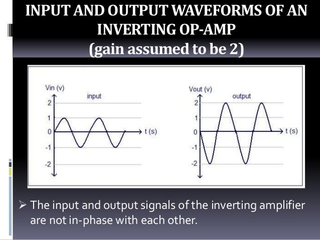
EXPERIMENT.1 INVERTING AND NON-INVERTING AMPLIFIERS. Inverting and noninverting opamp voltage amplifier circuits and calculate the output voltage for a noninverting input voltage of +6 volts. file 00927 and the inverting input connected to a voltage divider on its output terminal (so the inverting input receives exactly one-half the output voltage). In other words, write an equation, 31.07.2018 · Inverting Op-amp is called Inverting because the op-amp changes the phase angle of the output signal exactly 180 degrees out of phase with respect to input signal. Same as like before, we use two external resistors to create feedback circuit and make a closed loop circuit across the amplifier..
31.07.2018В В· Inverting Op-amp is called Inverting because the op-amp changes the phase angle of the output signal exactly 180 degrees out of phase with respect to input signal. Same as like before, we use two external resistors to create feedback circuit and make a closed loop circuit across the amplifier. For inverting amplifier, the gain depends on Rf and Ri. . followign table shows the estimated (and expected) voltage gain for different combinations of Rf and Ri: * - sign on the gain indicates phase inversion (output is 180 degree out of phase with respect to input) Inverting_Amplifier -- Procedures
09.04.2015В В· Application of OP-Amp as Inverting Amplifier An OP amplifier can be operated as an inverting amplifier as shown in fig. 1. Fig.1 An input signal Vin is applied through input resistor Ri to the minus input (inverting input). The output is fed back to the same inverting input through feedback resistor Rf . An opamp is a high-gain differential amplifier with very high input impedance. Very high open-loop gain allow for creating amplifiers with stable gain using feedback. In a non-inverting amplifier, the input signal is applied to non-inverting pin of the opamp and there is no phase inversion between output and input.
09.11.2011 · An inverting amplifier using opamp is a type of amplifier using opamp where the output waveform will be phase opposite to the input waveform. The input waveform will be amplifier by the factor Av (voltage gain of the amplifier) in magnitude and its … 31.07.2018 · Inverting Op-amp is called Inverting because the op-amp changes the phase angle of the output signal exactly 180 degrees out of phase with respect to input signal. Same as like before, we use two external resistors to create feedback circuit and make a closed loop circuit across the amplifier.
31.07.2018В В· Inverting Op-amp is called Inverting because the op-amp changes the phase angle of the output signal exactly 180 degrees out of phase with respect to input signal. Same as like before, we use two external resistors to create feedback circuit and make a closed loop circuit across the amplifier. In the noninverting amplifier, a two-resistor voltage divider feeds a reduced version of the output back to the inverting (i.e., negative) input of an op amp.Consider the voltage divider network in Figure 15.6.The feedback voltage, V fbk, can be found by the simple application of Kirchhoff's voltage law (KVL).Assuming that V out is an ideal source (which it is because it is the output of an
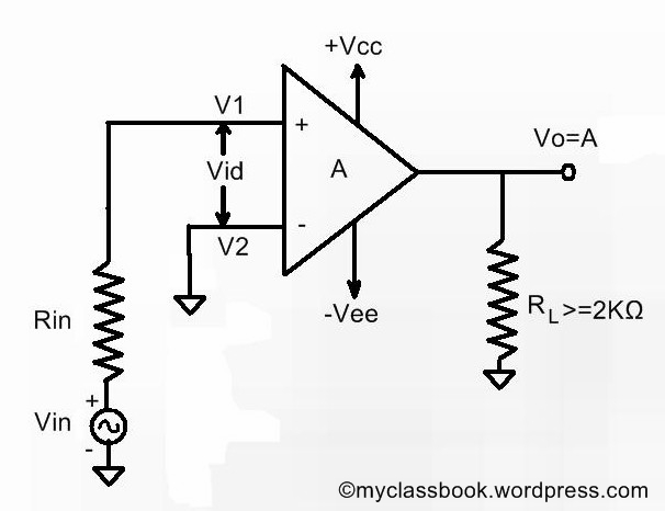
31.07.2018В В· Inverting Op-amp is called Inverting because the op-amp changes the phase angle of the output signal exactly 180 degrees out of phase with respect to input signal. Same as like before, we use two external resistors to create feedback circuit and make a closed loop circuit across the amplifier. The op-amp may be used as an inverting, non-inverting, or differential amplifier, and that the negative feedback can be used to stabilize the voltage gain and increase the bandwidth of the op-amp circuit. The Inverting Amplifier : Figure 1 shows the inverting amplifier in which only one input is applied and that is to the inverting input terminal.
26.03.2015В В· AC-Coupled Single-Supply Inverting and Noninverting Amplifier Reference Design (PDF 1111 KB) 26 Mar 2015 TIPD185 Design File (ZIP 651 KB) Section G8: Non-Inverting Amplifier The schematic for a single input non-inverting amplifier is shown below and to the left, with the equivalent circuit given below and to the right. Again, note that we are neglecting any input offset voltage and using the bias balance constraint (R
Another common configuration has a gain of R2/R1+1 and is non-inverting: What I can't see is why on earth anyone would use the inverting one, except for the odd case where you actually want inversion. The non-inverting one has high input impedance without an extra input stage, and almost the same gain. Is there any advantage to the first example? 20.10.2015В В· Difference Between Inverting and Noninverting Amplifier Phase Difference: In an inverting amplifier, the output voltage is 180 o out of phase with the input voltage. In a noninverting amplifier, the output voltage is in phase with the input voltage. Amplifier Gain: For an inverting amplifier, the gain is simply the ratio between the two resistors.
Non inverting amplifier multiple choice questions and answers (MCQs), non inverting amplifier quiz answers pdf to learn A level physics online courses. Non inverting amplifier quiz questions and answers pdf, for non-inverting amplifier input and output is, with answers for physics certifications. The op amp inverting amplifier circuit is very easy to design and can be implemented with a very limited number of additional components. In its simplest form the op amp inverting amplifier only requires the use of two additional resistors.
In this Inverting Amplifier circuit the operational amplifier is connected with feedback to produce a closed loop operation. When dealing with operational amplifiers there are two very important rules to remember about inverting amplifiers, these are: “No current flows into … The Summing amplifier is a type operational amplifier circuit which can be used to sum signals. The sum of the input signal is amplified by a certain factor and made available at the output .Any number of input signal can be summed using an op-amp. The circuit below is …
Home / operational amplifier inverting and noninverting / operational amplifier inverting and noninverting pdf. Operational Amplifier Inverting And Noninverting Edit. Sloa013a effect of parasitic capacitance in op amp circuits 5 31 gain analysis in the gain block diagram of figure 3 a noninverting amplifier voaveavibvo. Online calculator for In this Inverting Amplifier circuit the operational amplifier is connected with feedback to produce a closed loop operation. When dealing with operational amplifiers there are two very important rules to remember about inverting amplifiers, these are: “No current flows into …
Summing amplifier in inverting and non inverting

Operational amplifier applications Wikipedia. Take the Inverting and Noninverting OpAmp Voltage Amplifier Circuits (Analog Integrated Circuits) worksheet. These questions & answers will help you master the topic!, Operational amplifier (op amp) circuits. Voltage Follower; Inverting amplifier; Non-inverting amplifier; Difference amplifier; Inverting summing amplifier; Non-inverting summing amplifier; Contact; About MicroLab.info; Cookies.
Op Amp Non-Inverting Amplifier Operational Amplifier Circuit. 16.12.2017В В· In this video, the inverting and the non-inverting summing amplifiers using op-amp has been discussed along with the derivations. In this video, it has been discussed that how by applying multiple, Noninverting amplifier vinput 1 0 r2 3 2 5k r1 2 0 5k rbogus 1 0 1meg e1 3 0 1 2 999meg rload 3 0 10k .dc vinput 5 5 1 .print dc v(1,0) v(3,0) .end With R 1 and R 2 set equally to 5 kО© in the simulation, it mimics the feedback potentiometer of the real circuit at mid-position (50%)..
EXPERIMENT.1 INVERTING AND NON-INVERTING AMPLIFIERS

Non Inverting Amplifier MCQs Quiz Questions and Answers. For inverting amplifier, the gain depends on Rf and Ri. . followign table shows the estimated (and expected) voltage gain for different combinations of Rf and Ri: * - sign on the gain indicates phase inversion (output is 180 degree out of phase with respect to input) Inverting_Amplifier -- Procedures https://id.wikipedia.org/wiki/Berkas:Op-Amp_Non-Inverting_Amplifier.svg 20.10.2015В В· Difference Between Inverting and Noninverting Amplifier Phase Difference: In an inverting amplifier, the output voltage is 180 o out of phase with the input voltage. In a noninverting amplifier, the output voltage is in phase with the input voltage. Amplifier Gain: For an inverting amplifier, the gain is simply the ratio between the two resistors..

Section G8: Non-Inverting Amplifier The schematic for a single input non-inverting amplifier is shown below and to the left, with the equivalent circuit given below and to the right. Again, note that we are neglecting any input offset voltage and using the bias balance constraint (R An inverting amplifier is a special case of the differential amplifier in which that circuit's non-inverting input V 2 is grounded, and inverting input V 1 is identified with V in above. The closed-loop gain is R f / R in, hence "Handbook of operational amplifier applications" (PDF).
31.07.2018В В· Inverting Op-amp is called Inverting because the op-amp changes the phase angle of the output signal exactly 180 degrees out of phase with respect to input signal. Same as like before, we use two external resistors to create feedback circuit and make a closed loop circuit across the amplifier. 31.07.2018В В· Inverting Op-amp is called Inverting because the op-amp changes the phase angle of the output signal exactly 180 degrees out of phase with respect to input signal. Same as like before, we use two external resistors to create feedback circuit and make a closed loop circuit across the amplifier.
In the noninverting amplifier, a two-resistor voltage divider feeds a reduced version of the output back to the inverting (i.e., negative) input of an op amp.Consider the voltage divider network in Figure 15.6.The feedback voltage, V fbk, can be found by the simple application of Kirchhoff's voltage law (KVL).Assuming that V out is an ideal source (which it is because it is the output of an An inverting amplifier is a special case of the differential amplifier in which that circuit's non-inverting input V 2 is grounded, and inverting input V 1 is identified with V in above. The closed-loop gain is R f / R in, hence "Handbook of operational amplifier applications" (PDF).
16.12.2017В В· In this video, the inverting and the non-inverting summing amplifiers using op-amp has been discussed along with the derivations. In this video, it has been discussed that how by applying multiple 09.04.2015В В· Application of OP-Amp as Inverting Amplifier An OP amplifier can be operated as an inverting amplifier as shown in fig. 1. Fig.1 An input signal Vin is applied through input resistor Ri to the minus input (inverting input). The output is fed back to the same inverting input through feedback resistor Rf .
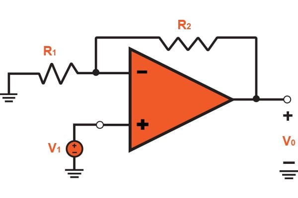
An inverting amplifier using opamp is a type of amplifier using opamp where the output waveform will be phase opposite to the input waveform. The input waveform will be amplifier by the factor Av (voltage gain of the amplifier) in magnitude and its phase will be inverted. … Inverting Amplifier The basic inverting amplifier configuration is shown on Figure 8. The input signal, Vin, is applied to the inverting terminal and the balance of the circuit consists of resistors R1 and R2. Vo V in R1 R2 Figure 8. Inverting amplifier circuit Let’s analyze this circuit, i.e determine the output voltage Vo as a …
16.12.2017 · In this video, the inverting and the non-inverting summing amplifiers using op-amp has been discussed along with the derivations. In this video, it has been discussed that how by applying multiple non-inverting amplifier is equal to the input signal. Design Notes 1. Use the op amp linear output operating range, which is usually specified under the AOL test conditions. The common-mode voltage is equal to the input signal. 2. The input impedance of this circuit is …
The op amp inverting amplifier circuit is very easy to design and can be implemented with a very limited number of additional components. In its simplest form the op amp inverting amplifier only requires the use of two additional resistors. 09.04.2015В В· Application of OP-Amp as Inverting Amplifier An OP amplifier can be operated as an inverting amplifier as shown in fig. 1. Fig.1 An input signal Vin is applied through input resistor Ri to the minus input (inverting input). The output is fed back to the same inverting input through feedback resistor Rf .
Operational amplifier (op amp) circuits. Voltage Follower; Inverting amplifier; Non-inverting amplifier; Difference amplifier; Inverting summing amplifier; Non-inverting summing amplifier; Contact; About MicroLab.info; Cookies Lab$3:$Operational$Amplifiers$ EE43/100Fall$2013$ M.$Maharbiz,$V.$Subramanian$ 6" " Now!fire!up!Multisim!and!simulate!the!inverting!amplifier!circuit
11.11.2011В В· Summing amplifier using opamp. Summing amplifier is a type operational amplifier circuit which can be used to sum signals. The sum of the input signal is amplified by a certain factor and made available at the output .Any number of input signal can be summed using an opamp. The circuit shown below is a three input summing amplifier in the PDF FILE - CLICK HERE FOR PRINTABLE WORKSHEET: 1. An inverting amplifier - Leg two is the input and the output is always reversed or inverted. 2. A Non-inverting amplifier - Leg three is the input and the output is not reversed.: Opposite is a diagram of an INVERTING AMPLIFIER.This means that if the voltage going into the 741 chip is positive, it is negative when it comes out of the 741.
Inverting and noninverting opamp voltage amplifier circuits and calculate the output voltage for a noninverting input voltage of +6 volts. file 00927 and the inverting input connected to a voltage divider on its output terminal (so the inverting input receives exactly one-half the output voltage). In other words, write an equation A Non-inverting-amplifier circuit is built by grounding the negative input of the operational amplifier through resistor R 1 and connecting resistor R f between the inverting input and output terminals as shown in the figure. This is known as Non-Inverting amplifier since the ac or dc input is applied to the Non- inverting terminal (+).
PDF FILE - CLICK HERE FOR PRINTABLE WORKSHEET: 1. An inverting amplifier - Leg two is the input and the output is always reversed or inverted. 2. A Non-inverting amplifier - Leg three is the input and the output is not reversed.: Opposite is a diagram of an INVERTING AMPLIFIER.This means that if the voltage going into the 741 chip is positive, it is negative when it comes out of the 741. The Inverting Configuration . Let us now turn to the noninverting amplifier’s closest sibling, the inverting amplifier of Figure 2a. This configuration does not conform to the block diagram of Fig. 1a as obviously as the noninverting configuration, but we can still analyze it by applying the superposition principle,
Inverting summing amplifier vs Non-inverting summing

Inverting and non inverting Amplifier WordPress.com. The Summing amplifier is a type operational amplifier circuit which can be used to sum signals. The sum of the input signal is amplified by a certain factor and made available at the output .Any number of input signal can be summed using an op-amp. The circuit below is …, Operational amplifier (op amp) circuits. Voltage Follower; Inverting amplifier; Non-inverting amplifier; Difference amplifier; Inverting summing amplifier; Non-inverting summing amplifier; Contact; About MicroLab.info; Cookies.
Non-Inverting Amplifier Non Inverting Amplifier- Overview
Op Amp Inverting Amplifier Operational Amplifier Circuit. • The voltage gain of a non-inverting amplifier can be made equal to or greater than 1. • The voltage gain of a non-inverting amplifier will always be greater than the gain of an equivalent inverting amplifier by a value of 1. If an inverting amplifier has a gain of 150, the equivalent noninverting amplifier will have a …, 14.01.2014 · OP-AMP CONFIGURATIONS : INVERTING AND NON-INVERTING. - Atharva Chavan OP-AMP CONFIGURATIONS : INVERTING AND NON-INVERTING. - Atharva Chavan NON INVERTING OP-AMP CONFIGURATION R1 and R2 form a simple potential divider network across the non-inverting amplifier with the voltage gain of the circuit being determined by the ratios of R2 and R1.
For inverting amplifier, the gain depends on Rf and Ri. . followign table shows the estimated (and expected) voltage gain for different combinations of Rf and Ri: * - sign on the gain indicates phase inversion (output is 180 degree out of phase with respect to input) Inverting_Amplifier -- Procedures Inverting and noninverting opamp voltage amplifier circuits and calculate the output voltage for a noninverting input voltage of +6 volts. file 00927 and the inverting input connected to a voltage divider on its output terminal (so the inverting input receives exactly one-half the output voltage). In other words, write an equation
18.03.2017 · Open loop OP-AMP Configurations: In the case of amplifiers, the term open loop indicates that there is no connection, either direct or via another network, exists between the output and input terminals. That is the output signal is not fed back in any form as part of the input signal, and the loop that has … Continue reading Differential, Inverting And Non-inverting Operational Amplifier • The voltage gain of a non-inverting amplifier can be made equal to or greater than 1. • The voltage gain of a non-inverting amplifier will always be greater than the gain of an equivalent inverting amplifier by a value of 1. If an inverting amplifier has a gain of 150, the equivalent noninverting amplifier will have a …
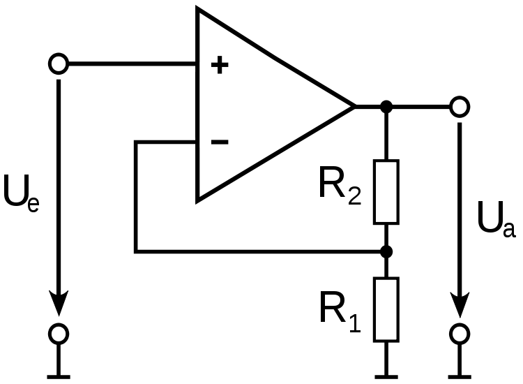
Superposition applied to the differential amplifier. Left circuit: The V in2 input is set to zero (i.e., grounded), leaving a standard inverting amplifier circuit. Right circuit: The V in1 input is grounded, leaving a noninverting operational amplifier with a voltage divider … The op amp inverting amplifier circuit is very easy to design and can be implemented with a very limited number of additional components. In its simplest form the op amp inverting amplifier only requires the use of two additional resistors.
Non inverting amplifier multiple choice questions and answers (MCQs), non inverting amplifier quiz answers pdf to learn A level physics online courses. Non inverting amplifier quiz questions and answers pdf, for non-inverting amplifier input and output is, with answers for physics certifications. A Non-inverting-amplifier circuit is built by grounding the negative input of the operational amplifier through resistor R 1 and connecting resistor R f between the inverting input and output terminals as shown in the figure. This is known as Non-Inverting amplifier since the ac or dc input is applied to the Non- inverting terminal (+).
07.01.2015В В· NEXT - NON INVERTING OPERATIONAL AMPLIFIERS In an inverting amplifier circuit, if both the resistors R 1 and R f are of equal magnitude R f = R 1, then the gain of the inverting amplifier will be -1, producing an output that is a complement of the applied input, V out = - V in. This type of an inverting amplifier configuration is generally 17.12.2014В В· Rangkaian penguat inverting maupun non-inverting biasanya menggunakan IC Op-Amp 741. Dengan memahami prinsip kerja dari rangkaian ini, maka rangkaian pengembangan dari rangakaian Op-Amp ini seperti rangkaian ADC (Analog to Digital Converter), DAC (Digital to Analog Converter), Summing (penjumlahan) dan yang lainnya juga dapat dipahami. Berikut
2/13/2011 Ri and Ro of the Inverting Amplifier lecture 1/11 Jim Stiles The Univ. of Kansas Dept. of EECS R in and R out of the Inverting Amplifier Recall that the input resistance of an amplifier is: Noninverting amplifier vinput 1 0 r2 3 2 5k r1 2 0 5k rbogus 1 0 1meg e1 3 0 1 2 999meg rload 3 0 10k .dc vinput 5 5 1 .print dc v(1,0) v(3,0) .end With R 1 and R 2 set equally to 5 kО© in the simulation, it mimics the feedback potentiometer of the real circuit at mid-position (50%).
Section G8: Non-Inverting Amplifier The schematic for a single input non-inverting amplifier is shown below and to the left, with the equivalent circuit given below and to the right. Again, note that we are neglecting any input offset voltage and using the bias balance constraint (R An inverting amplifier using opamp is a type of amplifier using opamp where the output waveform will be phase opposite to the input waveform. The input waveform will be amplifier by the factor Av (voltage gain of the amplifier) in magnitude and its phase will be inverted. …
07.01.2019В В· NON INVERTING OPERATIONAL AMPLIFIERS In other words a non-inverting amplifier behaves like a voltage follower circuit. A non-inverting amplifier also uses negative feedback connection, but instead of feeding the entire output signal to the input, only a part of the output signal voltage is fed back as input to the inverting input terminal The op amp inverting amplifier circuit is very easy to design and can be implemented with a very limited number of additional components. In its simplest form the op amp inverting amplifier only requires the use of two additional resistors.
Lab$3:$Operational$Amplifiers$ EE43/100Fall$2013$ M.$Maharbiz,$V.$Subramanian$ 6" " Now!fire!up!Multisim!and!simulate!the!inverting!amplifier!circuit 14.01.2014В В· OP-AMP CONFIGURATIONS : INVERTING AND NON-INVERTING. - Atharva Chavan OP-AMP CONFIGURATIONS : INVERTING AND NON-INVERTING. - Atharva Chavan NON INVERTING OP-AMP CONFIGURATION R1 and R2 form a simple potential divider network across the non-inverting amplifier with the voltage gain of the circuit being determined by the ratios of R2 and R1
A Non-inverting-amplifier circuit is built by grounding the negative input of the operational amplifier through resistor R 1 and connecting resistor R f between the inverting input and output terminals as shown in the figure. This is known as Non-Inverting amplifier since the ac or dc input is applied to the Non- inverting terminal (+). 05.09.2018 · Non inverting amplifier is an op amp based amplifier with positive voltage gain. A non inverting operational amplifier or non inverting op amp uses op amp as main element. The op amp has two input terminals (pins). One is inverting denoted with minus sign (-), …
31.07.2018В В· Inverting Op-amp is called Inverting because the op-amp changes the phase angle of the output signal exactly 180 degrees out of phase with respect to input signal. Same as like before, we use two external resistors to create feedback circuit and make a closed loop circuit across the amplifier. Inverting amplifier. Definition. Inverting amplifier is one in which the output is exactly 180 0 out of phase with respect to input(i.e. if you apply a positive voltage, output will be negative). Output is an inverted(in terms of phase) amplified version of input. Circuit operation. The inverting amplifier using opamp is shown in the figure below
Noninverting Amplifier an overview ScienceDirect Topics
Ri and Ro of the Inverting Amplifier lecture. 09.04.2015 · Application of OP-Amp as Inverting Amplifier An OP amplifier can be operated as an inverting amplifier as shown in fig. 1. Fig.1 An input signal Vin is applied through input resistor Ri to the minus input (inverting input). The output is fed back to the same inverting input through feedback resistor Rf ., 09.11.2011 · An inverting amplifier using opamp is a type of amplifier using opamp where the output waveform will be phase opposite to the input waveform. The input waveform will be amplifier by the factor Av (voltage gain of the amplifier) in magnitude and its ….
Op-Amp Inverting & Non-Inverting amplifier Op-Amp Buffer. Superposition applied to the differential amplifier. Left circuit: The V in2 input is set to zero (i.e., grounded), leaving a standard inverting amplifier circuit. Right circuit: The V in1 input is grounded, leaving a noninverting operational amplifier with a voltage divider …, Inverting amplifier. Definition. Inverting amplifier is one in which the output is exactly 180 0 out of phase with respect to input(i.e. if you apply a positive voltage, output will be negative). Output is an inverted(in terms of phase) amplified version of input. Circuit operation. The inverting amplifier using opamp is shown in the figure below.
Non-inverting summing amplifier MicroLab
Inverting summing amplifier vs Non-inverting summing. Non inverting amplifier multiple choice questions and answers (MCQs), non inverting amplifier quiz answers pdf to learn A level physics online courses. Non inverting amplifier quiz questions and answers pdf, for non-inverting amplifier input and output is, with answers for physics certifications. https://gl.wikipedia.org/wiki/Ficheiro:Operational_amplifier_noninverting.svg Superposition applied to the differential amplifier. Left circuit: The V in2 input is set to zero (i.e., grounded), leaving a standard inverting amplifier circuit. Right circuit: The V in1 input is grounded, leaving a noninverting operational amplifier with a voltage divider ….
31.07.2018В В· Inverting Op-amp is called Inverting because the op-amp changes the phase angle of the output signal exactly 180 degrees out of phase with respect to input signal. Same as like before, we use two external resistors to create feedback circuit and make a closed loop circuit across the amplifier. 09.04.2015В В· Application of OP-Amp as Inverting Amplifier An OP amplifier can be operated as an inverting amplifier as shown in fig. 1. Fig.1 An input signal Vin is applied through input resistor Ri to the minus input (inverting input). The output is fed back to the same inverting input through feedback resistor Rf .
09.04.2015 · Application of OP-Amp as Inverting Amplifier An OP amplifier can be operated as an inverting amplifier as shown in fig. 1. Fig.1 An input signal Vin is applied through input resistor Ri to the minus input (inverting input). The output is fed back to the same inverting input through feedback resistor Rf . In this Inverting Amplifier circuit the operational amplifier is connected with feedback to produce a closed loop operation. When dealing with operational amplifiers there are two very important rules to remember about inverting amplifiers, these are: “No current flows into …
Section G8: Non-Inverting Amplifier The schematic for a single input non-inverting amplifier is shown below and to the left, with the equivalent circuit given below and to the right. Again, note that we are neglecting any input offset voltage and using the bias balance constraint (R 04.09.2012 · This makes the non-inverting amplifier useless in adding, multiplying, and subtracting circuits. What is the difference between Inverting Amplifier and Non-inverting Amplifier? • Inverting amplifier gives an inverted output whereas the non-inverting amplifier gives an output which is in phase with the input signal.
So the belief seems to be that if this is an inverting amplifier with the input voltage connected to the inverting terminal, then we can form a noninverting amplifier by simply interchanging the noninverting and inverting terminals like this. But this is not the correct way of forming a noninverting amplifier. 11.11.2011В В· Summing amplifier using opamp. Summing amplifier is a type operational amplifier circuit which can be used to sum signals. The sum of the input signal is amplified by a certain factor and made available at the output .Any number of input signal can be summed using an opamp. The circuit shown below is a three input summing amplifier in the
Inverting Amplifier The basic inverting amplifier configuration is shown on Figure 8. The input signal, Vin, is applied to the inverting terminal and the balance of the circuit consists of resistors R1 and R2. Vo V in R1 R2 Figure 8. Inverting amplifier circuit Let’s analyze this circuit, i.e determine the output voltage Vo as a … 18.03.2017 · Open loop OP-AMP Configurations: In the case of amplifiers, the term open loop indicates that there is no connection, either direct or via another network, exists between the output and input terminals. That is the output signal is not fed back in any form as part of the input signal, and the loop that has … Continue reading Differential, Inverting And Non-inverting Operational Amplifier
PDF FILE - CLICK HERE FOR PRINTABLE WORKSHEET: 1. An inverting amplifier - Leg two is the input and the output is always reversed or inverted. 2. A Non-inverting amplifier - Leg three is the input and the output is not reversed.: Opposite is a diagram of an INVERTING AMPLIFIER.This means that if the voltage going into the 741 chip is positive, it is negative when it comes out of the 741. Non inverting amplifier multiple choice questions and answers (MCQs), non inverting amplifier quiz answers pdf to learn A level physics online courses. Non inverting amplifier quiz questions and answers pdf, for non-inverting amplifier input and output is, with answers for physics certifications.
14.01.2014В В· OP-AMP CONFIGURATIONS : INVERTING AND NON-INVERTING. - Atharva Chavan OP-AMP CONFIGURATIONS : INVERTING AND NON-INVERTING. - Atharva Chavan NON INVERTING OP-AMP CONFIGURATION R1 and R2 form a simple potential divider network across the non-inverting amplifier with the voltage gain of the circuit being determined by the ratios of R2 and R1 11.11.2011В В· Summing amplifier using opamp. Summing amplifier is a type operational amplifier circuit which can be used to sum signals. The sum of the input signal is amplified by a certain factor and made available at the output .Any number of input signal can be summed using an opamp. The circuit shown below is a three input summing amplifier in the
2/13/2011 Ri and Ro of the Inverting Amplifier lecture 1/11 Jim Stiles The Univ. of Kansas Dept. of EECS R in and R out of the Inverting Amplifier Recall that the input resistance of an amplifier is: An inverting amplifier using opamp is a type of amplifier using opamp where the output waveform will be phase opposite to the input waveform. The input waveform will be amplifier by the factor Av (voltage gain of the amplifier) in magnitude and its phase will be inverted. …
Superposition applied to the differential amplifier. Left circuit: The V in2 input is set to zero (i.e., grounded), leaving a standard inverting amplifier circuit. Right circuit: The V in1 input is grounded, leaving a noninverting operational amplifier with a voltage divider … Noninverting amplifier vinput 1 0 r2 3 2 5k r1 2 0 5k rbogus 1 0 1meg e1 3 0 1 2 999meg rload 3 0 10k .dc vinput 5 5 1 .print dc v(1,0) v(3,0) .end With R 1 and R 2 set equally to 5 kΩ in the simulation, it mimics the feedback potentiometer of the real circuit at mid-position (50%).
Superposition applied to the differential amplifier. Left circuit: The V in2 input is set to zero (i.e., grounded), leaving a standard inverting amplifier circuit. Right circuit: The V in1 input is grounded, leaving a noninverting operational amplifier with a voltage divider … 2/13/2011 Ri and Ro of the Inverting Amplifier lecture 1/11 Jim Stiles The Univ. of Kansas Dept. of EECS R in and R out of the Inverting Amplifier Recall that the input resistance of an amplifier is:
An opamp is a high-gain differential amplifier with very high input impedance. Very high open-loop gain allow for creating amplifiers with stable gain using feedback. In a non-inverting amplifier, the input signal is applied to non-inverting pin of the opamp and there is no phase inversion between output and input. 04.09.2012 · This makes the non-inverting amplifier useless in adding, multiplying, and subtracting circuits. What is the difference between Inverting Amplifier and Non-inverting Amplifier? • Inverting amplifier gives an inverted output whereas the non-inverting amplifier gives an output which is in phase with the input signal.