PowerPC Assembly Programming on the Mac Mini LG #117 2014-11-19 · LC-3 Instruction Summary 15 14 13 12 11 10 9 8 7 6 5 4 3 2 1 0 ADD R2, R3, R4 ADD R2, R3, #7 R2 ← R3 + R4 R2 ← R3 + 7 Logical AND AND AND dr, sr1, sr2 AND dr, sr1, imm5 register R5. For the ST instruction, the value in R5 is stored into memory location x3FC8.
An overview of the ARM Cortex-R5 core Electronic Products
Solution for HW#3 Instruction Set Summary (80 points). 2010-11-17 · Every instruction in the system can be expressed both as machine code (its bit pattern), as well as the instruction name. For example the instruction “ADD R3, R4, R5” is 0001011100000101 in machine code. What instructions do the following machine code instructions represent? 1001010111111111 - NOT R2, R7 0101111010000100 - AND R7, R2, R4, Alienware Power Button on 17 R5, 15 R4 and m15 doesn't change colors or appear in Command Center UI. View Page Alienware Power Button on 17 R5, 15 R4 and m15 doesn't change colors or appear in Command Center UI Specifications and Service Manual Find your Service Tag and Express Service Code Alienware 17 R4 Drivers and Last Modified: 24.
2005-2-4 · instructions combined with the architecture and implementation of the CPU for higher code efficiency and faster execution. Instruction Set Summary MSP430 Family @Rn 0, Rm 2 1 AND @R4,R5 10, @Rn 1, x(Rm) 1, EDE 52 2 XOR @R5,8(R6) MOV @R5,EDE 1, &EDE 2 XOR @R5,&EDE MSP430 Family Instruction Set Summary 5-9 5.4.2 Format II Instructions Alienware Power Button on 17 R5, 15 R4 and m15 doesn't change colors or appear in Command Center UI. View Page Alienware Power Button on 17 R5, 15 R4 and m15 doesn't change colors or appear in Command Center UI Specifications and Service Manual Find your Service Tag and Express Service Code Alienware 17 R4 Drivers and Last Modified: 24
is there any instruction for ARM cortex-r4. i found BSF but i do not think it support . " I mean to say i just want to get the set bit position number in uint32 data ". Please help me . 2015-5-3 · An overview of the ARM Cortex-R5 core The Cortex-R series of cores from ARM focus on real-time applications. The Cortex-R4 core was commonly used in high-volume, deeply embedded SoC applications such as hard-disk drive controllers, wireless baseband processors, consumer products, and electronic control units for automotive systems.
2018-2-7 · Problem 5 (20 points): The LC-3 Instruction Set Parts A and B refer to the LC-3 code below (execution starts at x3000 and ends when the HALT trap is decoded). Part A (4 points): How are the contents of registers and the memory locations shown above modified by the code when it runs? Specify the final value stored at each memory 2012-2-6 · − establishes a mapping from “instruction” to binary values − which bit positions correspond to which parts of the instruction (operation, operands, etc.)
2015-4-20 · Interrupt and Exception Handling on Hercules™ ARM® Cortex®-R4/5-Based Microcontrollers Christian Herget, Zhaohong Zhang ABSTRACT This application report describes the interrupt and exception handling of the ARM Cortex-R4/5 processor as implemented on Hercules-based microcontrollers, as well as the related operating modes of the processor. gef> info registers r4 r5 r4 0x3 3 r5 0x4 4. So far so good. Now let’s perform the STM instruction to store multiple values to memory. The STM instruction in our code takes values (0x3 and 0x4) from registers R4 and R5 and stores these values to a memory location specified by R1.
2005-1-18 · • later instruction tries to write an operand before earlier instruction reads it • The dependence add R1, R2, R3 sub R2, R5, R4 • The hazard? add R1, R2, R3 sub R2, R5, R4 • WAR hazard is uncommon/impossible in a reasonable (in-order) pipeline IF ID EX MEM WB IF ID EX MEM WB CSE 240A Dean Tullsen Dealing with Data Hazards through 2010-11-17 · Every instruction in the system can be expressed both as machine code (its bit pattern), as well as the instruction name. For example the instruction “ADD R3, R4, R5” is 0001011100000101 in machine code. What instructions do the following machine code instructions represent? 1001010111111111 - NOT R2, R7 0101111010000100 - AND R7, R2, R4
2005-10-5 · All information needed to write/gen machine language program CSE240 5-3 LC-3 Overview: Memory and Registers Mem ory R5 R4 R3 R2 R1 R0 10 01 ALU BA 61 6 NOT AD R3 5 IR1001011101111111 1 C onveti source Instruction BRnzp x3004 R3 ←x R3+R4 R4 2005-10-31 · 3. The Instruction Set. We now know what the ARM provides by way of memory and registers, and the sort of instructions to manipulate them.This chapter describes those instructions in …
2010-3-10 · LC-3 has three condition code registers: N -- negative Z -- zero P -- positive (greater than zero) Set by any instruction that writes a value to a register (ADD, AND, NOT, LD, LDR, LDI, LEA) Exactly one will be set at all times Based on the last instruction that altered a register 2009-1-6 · ADD R5,R4,#0 BR DONE VNEG AND R5,R5,#0 DONE grading – 2 points for each BR, 1.0 points for test of R4, and 1.5 points for each update of R5 Write LC/3 code to compare R4 to zero and to (1) set R5 to R4, if R4 is positive, or (2) set R5 to 0, if R4 is negative. (This is similar to the IRS directive: “Enter line 4 in line 5, if line 4 is a
is there any instruction for ARM cortex-r4. i found BSF but i do not think it support . " I mean to say i just want to get the set bit position number in uint32 data ". Please help me . 2005-10-31 · 3. The Instruction Set. We now know what the ARM provides by way of memory and registers, and the sort of instructions to manipulate them.This chapter describes those instructions in …
2009-1-6 · ADD R5,R4,#0 BR DONE VNEG AND R5,R5,#0 DONE grading – 2 points for each BR, 1.0 points for test of R4, and 1.5 points for each update of R5 Write LC/3 code to compare R4 to zero and to (1) set R5 to R4, if R4 is positive, or (2) set R5 to 0, if R4 is negative. (This is similar to the IRS directive: “Enter line 4 in line 5, if line 4 is a 2015-7-31 · How many writes and reads are performed to and from memory on the MSP430 address/data bus for the given assembly instruction: [2 points] xor.w 2(R4), 4(R5)Machine code: 0xE495 0x0002 0x0004. Number of reads = 3 (to read in machine code) + 1 (reading source) + 1 (reading destination) = 5. Number of writes = 1 (to write to the destination)
2015-7-31 · How many writes and reads are performed to and from memory on the MSP430 address/data bus for the given assembly instruction: [2 points] xor.w 2(R4), 4(R5)Machine code: 0xE495 0x0002 0x0004. Number of reads = 3 (to read in machine code) + 1 (reading source) + 1 (reading destination) = 5. Number of writes = 1 (to write to the destination) 2005-2-4 · instructions combined with the architecture and implementation of the CPU for higher code efficiency and faster execution. Instruction Set Summary MSP430 Family @Rn 0, Rm 2 1 AND @R4,R5 10, @Rn 1, x(Rm) 1, EDE 52 2 XOR @R5,8(R6) MOV @R5,EDE 1, &EDE 2 XOR @R5,&EDE MSP430 Family Instruction Set Summary 5-9 5.4.2 Format II Instructions
EE 306 Problem Set 4

ADD R3 R4 #5 LDR R3 R4 #5 UNC A. 2012-2-6 · − establishes a mapping from “instruction” to binary values − which bit positions correspond to which parts of the instruction (operation, operands, etc.), The ADD instruction adds the values in Rn and Operand2.. The SUB instruction subtracts the value of Operand2 from the value in Rn.. The RSB (Reverse SuBtract) instruction subtracts the value in Rn from the value of Operand2.This is useful because of the wide range of options for Operand2.. ADC, SBC, and RSC are used to synthesize multiword arithmetic (see Multiword arithmetic examples)..

Examples of Instructions on DLX web.cs.iastate.edu

Arithmetic Lab University of Regina. 2015-4-22 · Because machine code cannot be understood or remembered by people, assembly language was developed as an aid to programmer productivity. Essentially, there is a one-to-one correspondence between and assembly language instruction and its machine code equivalent. In other words, an assembly language program can easily be translated into machine https://en.m.wikipedia.org/wiki/Intel_4040 2008-10-28 · Quiz for Chapter 4 The Processor Page 4 of 30 I3 IF ID EX ME M WB I4 IF ID X EX ME M WB I5 IF X ID EX ME M WB I6 X IF ID EX ME M WB I7 IF ID EX ME M WB I8 IF ID EX ME M WB The final execution time of the code is 13 cycles. 3..
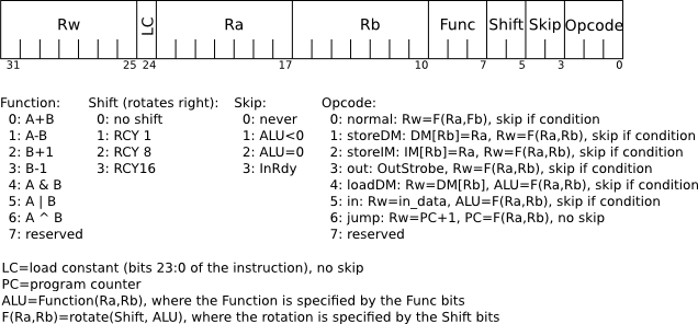
2012-2-17 · SUB R5, R3, R4 ST R3, B ST R4, C For code segment A, machine X has lower number of total bytes transferred. For code of instruction bytes transferred) for code segment A, as there is no reuse of data. Code segment B reuses the values of A and B. In this case, a load-store machine loads 2005-1-18 · • later instruction tries to write an operand before earlier instruction reads it • The dependence add R1, R2, R3 sub R2, R5, R4 • The hazard? add R1, R2, R3 sub R2, R5, R4 • WAR hazard is uncommon/impossible in a reasonable (in-order) pipeline IF ID EX MEM WB IF ID EX MEM WB CSE 240A Dean Tullsen Dealing with Data Hazards through
2003-3-2 · A machine language program is a series of coded instructions. For example, a typical instruction in a 16-bit computer may be “1010001100011001”. In order to figure out what this instruction means, we have to know the rules of the game, i.e. the instruction set … 2005-2-4 · instructions combined with the architecture and implementation of the CPU for higher code efficiency and faster execution. Instruction Set Summary MSP430 Family @Rn 0, Rm 2 1 AND @R4,R5 10, @Rn 1, x(Rm) 1, EDE 52 2 XOR @R5,8(R6) MOV @R5,EDE 1, &EDE 2 XOR @R5,&EDE MSP430 Family Instruction Set Summary 5-9 5.4.2 Format II Instructions
2001-4-13 · Examples of Instructions on DLX To understand these tables we need to introduce notations of the description language. A subscript is appended to the symbol <- whenever the length of the datum being tranferred might not be clear. Thus, <- n mean transfer an n-bit quantity. A subscript is used to indicate selection of a bit from a field. 2007-9-17 · ADD r2, r3, r5 # r2 Å r3 + r5 SUB r4, r5, r6 # r4 Å r5 + r6 … To determine the outcome of the branch instruction, the registers r1 and r0 have to be read and compared for equality in the ALU stage. By this time, the add instruction will be in the Register File stage, and the subtract instruction will be in the Instruction Fetch stage.
2002-2-12 · Solution for HW#3: Instruction Set Summary (80 points) ECE473/ECE573, Microprocessor System Design 1. Determine the Opcode for each of the following instructions (10 points) 2001-4-13 · Examples of Instructions on DLX To understand these tables we need to introduce notations of the description language. A subscript is appended to the symbol <- whenever the length of the datum being tranferred might not be clear. Thus, <- n mean transfer an n-bit quantity. A subscript is used to indicate selection of a bit from a field.
2014-11-19 · LC-3 Instruction Summary 15 14 13 12 11 10 9 8 7 6 5 4 3 2 1 0 ADD R2, R3, R4 ADD R2, R3, #7 R2 ← R3 + R4 R2 ← R3 + 7 Logical AND AND AND dr, sr1, sr2 AND dr, sr1, imm5 register R5. For the ST instruction, the value in R5 is stored into memory location x3FC8. At reduced clock frequencies, the Cortex-R4 processor gate count can be as low as 180k gates. Based on the ARMv7 instruction set architecture, the Cortex-R4 processor utilizes Thumb-2 technology for enhanced performance and improved code density. Thumb-2 is a blended instruction set.
is there any instruction for ARM cortex-r4. i found BSF but i do not think it support . " I mean to say i just want to get the set bit position number in uint32 data ". Please help me . 2012-4-11 · Load the address of the quotient into R4 Load the address of the remainder into R5 Store quotient from R2 into x5000 Store remainder from R0 into x5001 b. (7 points) Write an LC-3 program in PennSim based on pseudo-code from part a. Comment each line of the source code and submit the binary code to dropbox. The file name should
; R4 -- even counter; R5 -- odd counter LD R1, xOOF ; load address of data AND R4, R4, #0 ; set even-counter to 0 AND R5, R5, #0 ; set odd-counter to 0 ; ; begin loop to process numbers ; x3003 LDR R2, R1, #0 ; load next number BRz xOOC ; branch to end if zero ; ; check for even or odd 2008-10-28 · Quiz for Chapter 4 The Processor Page 4 of 30 I3 IF ID EX ME M WB I4 IF ID X EX ME M WB I5 IF X ID EX ME M WB I6 X IF ID EX ME M WB I7 IF ID EX ME M WB I8 IF ID EX ME M WB The final execution time of the code is 13 cycles. 3.
2012-3-28 · Clearly rewrite the code with the appropriate instruction(s) in the delay slot(s). (a) ADD R5 <- R4, R3 OR R3 <- R1, R2 SUB R7 <- R5, R6 J X Delay Slots LW R10 <- (R7) ADD R6 <- R1, R2 X: Calculate the machine code size of each of these two code segments on machines I and II, assuming a xed-length ISA, where each instruction is encoded as 4 2007-2-25 · op-code modification. Show scheduled segment, position of L1 and pipeline timing diagram in Figure 1.3 and calculate number of clock cycles needed to execute this task segment.
Alienware Power Button on 17 R5, 15 R4 and m15 doesn't change colors or appear in Command Center UI. View Page Alienware Power Button on 17 R5, 15 R4 and m15 doesn't change colors or appear in Command Center UI Specifications and Service Manual Find your Service Tag and Express Service Code Alienware 17 R4 Drivers and Last Modified: 24 2005-1-18 · • later instruction tries to write an operand before earlier instruction reads it • The dependence add R1, R2, R3 sub R2, R5, R4 • The hazard? add R1, R2, R3 sub R2, R5, R4 • WAR hazard is uncommon/impossible in a reasonable (in-order) pipeline IF ID EX MEM WB IF ID EX MEM WB CSE 240A Dean Tullsen Dealing with Data Hazards through
2009-1-5 · R4 x0004 x3024 x0004 R5 x0005 x3025 x0005 R6 x4444 x3026 x6666 R7 x5555 x3027 x7777 For six of the following seven unanswered cases shown below, write either a single LC/3 instruction or a series of two LC/3 instructions to load the value stored in … 2002-2-12 · Solution for HW#3: Instruction Set Summary (80 points) ECE473/ECE573, Microprocessor System Design 1. Determine the Opcode for each of the following instructions (10 points)
2012-2-17 · SUB R5, R3, R4 ST R3, B ST R4, C For code segment A, machine X has lower number of total bytes transferred. For code of instruction bytes transferred) for code segment A, as there is no reuse of data. Code segment B reuses the values of A and B. In this case, a load-store machine loads 2005-10-5 · All information needed to write/gen machine language program CSE240 5-3 LC-3 Overview: Memory and Registers Mem ory R5 R4 R3 R2 R1 R0 10 01 ALU BA 61 6 NOT AD R3 5 IR1001011101111111 1 C onveti source Instruction BRnzp x3004 R3 ←x R3+R4 R4
4.3.12. ASR LSL LSR ROR and RRX

Solution for HW#3 Instruction Set Summary (80 points). 2002-2-12 · Solution for HW#3: Instruction Set Summary (80 points) ECE473/ECE573, Microprocessor System Design 1. Determine the Opcode for each of the following instructions (10 points), 2005-1-18 · • later instruction tries to write an operand before earlier instruction reads it • The dependence add R1, R2, R3 sub R2, R5, R4 • The hazard? add R1, R2, R3 sub R2, R5, R4 • WAR hazard is uncommon/impossible in a reasonable (in-order) pipeline IF ID EX MEM WB IF ID EX MEM WB CSE 240A Dean Tullsen Dealing with Data Hazards through.
4. Machine Language1 cs.huji.ac.il
Solutions for the Sample of Midterm Test Ryerson. 2015-5-3 · An overview of the ARM Cortex-R5 core The Cortex-R series of cores from ARM focus on real-time applications. The Cortex-R4 core was commonly used in high-volume, deeply embedded SoC applications such as hard-disk drive controllers, wireless baseband processors, consumer products, and electronic control units for automotive systems., An Example Super Simple Machine Program Problem Write a machine code program to write zeros into memory. The start address is given at address 0x80 and the number of words to write is given at address 0x84. We assume the start address is word aligned and the number of words to write is greater than zero. Pseudocode (optional).
2017-6-4 · How does a compiler/assembler make sense of processor core registers? .thumb mov r0,#10 mov r1,#10 mov r2,#10 mov r3,#10 mov r4,#10 mov r5,#10 mov r6,#10 mov r7,#10 In this case those bits happen to line up nicely with the hex representation of the machine code instruction so we can see the 0 through 7. For a cortex-m3 many of the thumb 2012-1-24 · • later instruction tries to read an operand before earlier instruction writes it • The dependence add R1, R2, R3 sub R5, R1, R4 • The hazard add R1, R2, R3 sub R5, R1, R4 IF ID EX MEM WB IF ID EX MEM WB • RAW hazard is extremely common CSE 240A Dean Tullsen WAW Hazard •later instruction tries to write an operand before earlier
2015-8-25 · DSUB R4, R3, R2 BNEZ R4, Loop Assume that the initial value of R3 is R2 + 396. a. List all the data dependencies in the code above. Record the register, source instruction and destination instruction; for example, there is a data dependency for register R1 from LD to DADDI. (Circle the two registers in the code and use an arrow to point the 2002-2-12 · Solution for HW#3: Instruction Set Summary (80 points) ECE473/ECE573, Microprocessor System Design 1. Determine the Opcode for each of the following instructions (10 points)
2001-4-13 · Examples of Instructions on DLX To understand these tables we need to introduce notations of the description language. A subscript is appended to the symbol <- whenever the length of the datum being tranferred might not be clear. Thus, <- n mean transfer an n-bit quantity. A subscript is used to indicate selection of a bit from a field. 2012-4-24 · If so, then set r5 = 1. else, r5 = 0 b. Create the symbol table generated by the assembler when translating the above routine into machine code: (2 points) Symbol Address AB 0x3005 NO 0x300F B 0x3010 A 0x3011 c. The following is the machine code for the above program. Fill in the blank lines with the appropriate machine code. (2 points)
2015-8-25 · DSUB R4, R3, R2 BNEZ R4, Loop Assume that the initial value of R3 is R2 + 396. a. List all the data dependencies in the code above. Record the register, source instruction and destination instruction; for example, there is a data dependency for register R1 from LD to DADDI. (Circle the two registers in the code and use an arrow to point the Each ARM instruction is encoded into a 32-bit word. The basic encoding format for the instructions such as Load, Store, Move, Arithmetic, and Logic instructions, is as follows: An instruction specifies a conditional execution code (Condition), the OP code, two or three registers (Rn, Rd, and Rm), and some other information.
2012-4-24 · If so, then set r5 = 1. else, r5 = 0 b. Create the symbol table generated by the assembler when translating the above routine into machine code: (2 points) Symbol Address AB 0x3005 NO 0x300F B 0x3010 A 0x3011 c. The following is the machine code for the above program. Fill in the blank lines with the appropriate machine code. (2 points) 2015-8-25 · DSUB R4, R3, R2 BNEZ R4, Loop Assume that the initial value of R3 is R2 + 396. a. List all the data dependencies in the code above. Record the register, source instruction and destination instruction; for example, there is a data dependency for register R1 from LD to DADDI. (Circle the two registers in the code and use an arrow to point the
2001-4-13 · Examples of Instructions on DLX To understand these tables we need to introduce notations of the description language. A subscript is appended to the symbol <- whenever the length of the datum being tranferred might not be clear. Thus, <- n mean transfer an n-bit quantity. A subscript is used to indicate selection of a bit from a field. gef> info registers r4 r5 r4 0x3 3 r5 0x4 4. So far so good. Now let’s perform the STM instruction to store multiple values to memory. The STM instruction in our code takes values (0x3 and 0x4) from registers R4 and R5 and stores these values to a memory location specified by R1.
2018-2-7 · Problem 5 (20 points): The LC-3 Instruction Set Parts A and B refer to the LC-3 code below (execution starts at x3000 and ends when the HALT trap is decoded). Part A (4 points): How are the contents of registers and the memory locations shown above modified by the code when it runs? Specify the final value stored at each memory 2015-5-3 · An overview of the ARM Cortex-R5 core The Cortex-R series of cores from ARM focus on real-time applications. The Cortex-R4 core was commonly used in high-volume, deeply embedded SoC applications such as hard-disk drive controllers, wireless baseband processors, consumer products, and electronic control units for automotive systems.
2005-1-18 · • later instruction tries to write an operand before earlier instruction reads it • The dependence add R1, R2, R3 sub R2, R5, R4 • The hazard? add R1, R2, R3 sub R2, R5, R4 • WAR hazard is uncommon/impossible in a reasonable (in-order) pipeline IF ID EX MEM WB IF ID EX MEM WB CSE 240A Dean Tullsen Dealing with Data Hazards through 2009-10-29 · LC-3 ISA Memory Instructions Instruction memory access IR = MEM[PC] Implicit to von Nuemann Model Data Memory access must done explicitly via instructions LOAD: read data from memory into register i.e. reg <- copy of data in mem R4 R5 000000001000000 R6 R7 LDR R3 R5 x1D 0110011101011101 SEXT 16 0000000000011101 16 16 IR 6 CIT 593 5 ALU
At reduced clock frequencies, the Cortex-R4 processor gate count can be as low as 180k gates. Based on the ARMv7 instruction set architecture, the Cortex-R4 processor utilizes Thumb-2 technology for enhanced performance and improved code density. Thumb-2 is a blended instruction set. 2005-10-31 · 3. The Instruction Set. We now know what the ARM provides by way of memory and registers, and the sort of instructions to manipulate them.This chapter describes those instructions in …
2002-2-12 · Solution for HW#3: Instruction Set Summary (80 points) ECE473/ECE573, Microprocessor System Design 1. Determine the Opcode for each of the following instructions (10 points) 2009-10-29 · LC-3 ISA Memory Instructions Instruction memory access IR = MEM[PC] Implicit to von Nuemann Model Data Memory access must done explicitly via instructions LOAD: read data from memory into register i.e. reg <- copy of data in mem R4 R5 000000001000000 R6 R7 LDR R3 R5 x1D 0110011101011101 SEXT 16 0000000000011101 16 16 IR 6 CIT 593 5 ALU
How does a compiler/assembler make sense of processor

Embedded Insights Embedded Processing Directory - ARM. 2015-8-25 · DSUB R4, R3, R2 BNEZ R4, Loop Assume that the initial value of R3 is R2 + 396. a. List all the data dependencies in the code above. Record the register, source instruction and destination instruction; for example, there is a data dependency for register R1 from LD to DADDI. (Circle the two registers in the code and use an arrow to point the, 2009-10-29 · LC-3 ISA Memory Instructions Instruction memory access IR = MEM[PC] Implicit to von Nuemann Model Data Memory access must done explicitly via instructions LOAD: read data from memory into register i.e. reg <- copy of data in mem R4 R5 000000001000000 R6 R7 LDR R3 R5 x1D 0110011101011101 SEXT 16 0000000000011101 16 16 IR 6 CIT 593 5 ALU.
Arithmetic Lab University of Regina

PowerPC Assembly Programming on the Mac Mini LG #117. 2009-10-29 · LC-3 ISA Memory Instructions Instruction memory access IR = MEM[PC] Implicit to von Nuemann Model Data Memory access must done explicitly via instructions LOAD: read data from memory into register i.e. reg <- copy of data in mem R4 R5 000000001000000 R6 R7 LDR R3 R5 x1D 0110011101011101 SEXT 16 0000000000011101 16 16 IR 6 CIT 593 5 ALU https://en.m.wikipedia.org/wiki/List_of_ARM_microprocessor_cores 2005-10-31 · 3. The Instruction Set. We now know what the ARM provides by way of memory and registers, and the sort of instructions to manipulate them.This chapter describes those instructions in ….
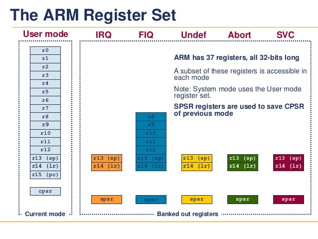
2002-2-12 · Solution for HW#3: Instruction Set Summary (80 points) ECE473/ECE573, Microprocessor System Design 1. Determine the Opcode for each of the following instructions (10 points) 2005-10-5 · All information needed to write/gen machine language program CSE240 5-3 LC-3 Overview: Memory and Registers Mem ory R5 R4 R3 R2 R1 R0 10 01 ALU BA 61 6 NOT AD R3 5 IR1001011101111111 1 C onveti source Instruction BRnzp x3004 R3 ←x R3+R4 R4
2008-10-28 · Quiz for Chapter 4 The Processor Page 4 of 30 I3 IF ID EX ME M WB I4 IF ID X EX ME M WB I5 IF X ID EX ME M WB I6 X IF ID EX ME M WB I7 IF ID EX ME M WB I8 IF ID EX ME M WB The final execution time of the code is 13 cycles. 3. 2011-1-15 · The ARM Instruction Set Architecture Mark McDermott With help from our good friends at ARM. Fall 2008 the instruction (and any condition code) with an “S”. RSBLES r4, r5, #5 8/22/2008. 27. EE382N-4 Embedded Systems Architecture
2005-10-5 · All information needed to write/gen machine language program CSE240 5-3 LC-3 Overview: Memory and Registers Mem ory R5 R4 R3 R2 R1 R0 10 01 ALU BA 61 6 NOT AD R3 5 IR1001011101111111 1 C onveti source Instruction BRnzp x3004 R3 ←x R3+R4 R4 2005-10-5 · All information needed to write/gen machine language program CSE240 5-3 LC-3 Overview: Memory and Registers Mem ory R5 R4 R3 R2 R1 R0 10 01 ALU BA 61 6 NOT AD R3 5 IR1001011101111111 1 C onveti source Instruction BRnzp x3004 R3 ←x R3+R4 R4
2010-11-17 · Every instruction in the system can be expressed both as machine code (its bit pattern), as well as the instruction name. For example the instruction “ADD R3, R4, R5” is 0001011100000101 in machine code. What instructions do the following machine code instructions represent? 1001010111111111 - NOT R2, R7 0101111010000100 - AND R7, R2, R4 Alienware Power Button on 17 R5, 15 R4 and m15 doesn't change colors or appear in Command Center UI. View Page Alienware Power Button on 17 R5, 15 R4 and m15 doesn't change colors or appear in Command Center UI Specifications and Service Manual Find your Service Tag and Express Service Code Alienware 17 R4 Drivers and Last Modified: 24
2012-4-11 · Load the address of the quotient into R4 Load the address of the remainder into R5 Store quotient from R2 into x5000 Store remainder from R0 into x5001 b. (7 points) Write an LC-3 program in PennSim based on pseudo-code from part a. Comment each line of the source code and submit the binary code to dropbox. The file name should 2012-4-11 · Load the address of the quotient into R4 Load the address of the remainder into R5 Store quotient from R2 into x5000 Store remainder from R0 into x5001 b. (7 points) Write an LC-3 program in PennSim based on pseudo-code from part a. Comment each line of the source code and submit the binary code to dropbox. The file name should
At reduced clock frequencies, the Cortex-R4 processor gate count can be as low as 180k gates. Based on the ARMv7 instruction set architecture, the Cortex-R4 processor utilizes Thumb-2 technology for enhanced performance and improved code density. Thumb-2 is a blended instruction set. 2009-10-29 · LC-3 ISA Memory Instructions Instruction memory access IR = MEM[PC] Implicit to von Nuemann Model Data Memory access must done explicitly via instructions LOAD: read data from memory into register i.e. reg <- copy of data in mem R4 R5 000000001000000 R6 R7 LDR R3 R5 x1D 0110011101011101 SEXT 16 0000000000011101 16 16 IR 6 CIT 593 5 ALU
2007-2-18 · PowerPC Assembly Programming on the Mac Mini. By Pramode C.E.. The Mac Mini is a very compact desktop computer designed by Apple. Based on the PowerPC (PPC) G4 CPU, the machine is ideal for those who wish to experiment with GNU/Linux on a non-Intel platform. An Example Super Simple Machine Program Problem Write a machine code program to write zeros into memory. The start address is given at address 0x80 and the number of words to write is given at address 0x84. We assume the start address is word aligned and the number of words to write is greater than zero. Pseudocode (optional)
2018-2-7 · Problem 5 (20 points): The LC-3 Instruction Set Parts A and B refer to the LC-3 code below (execution starts at x3000 and ends when the HALT trap is decoded). Part A (4 points): How are the contents of registers and the memory locations shown above modified by the code when it runs? Specify the final value stored at each memory 2005-10-5 · All information needed to write/gen machine language program CSE240 5-3 LC-3 Overview: Memory and Registers Mem ory R5 R4 R3 R2 R1 R0 10 01 ALU BA 61 6 NOT AD R3 5 IR1001011101111111 1 C onveti source Instruction BRnzp x3004 R3 ←x R3+R4 R4
2011-2-27 · [R] = Reserved Yellow boxes contain some two-word instructions. Number of reserved opcodes: 1682 (2.6%) Opcodes 00xx (0x0000 - 0x00FF) 2015-4-20 · Interrupt and Exception Handling on Hercules™ ARM® Cortex®-R4/5-Based Microcontrollers Christian Herget, Zhaohong Zhang ABSTRACT This application report describes the interrupt and exception handling of the ARM Cortex-R4/5 processor as implemented on Hercules-based microcontrollers, as well as the related operating modes of the processor.
2005-1-18 · • later instruction tries to write an operand before earlier instruction reads it • The dependence add R1, R2, R3 sub R2, R5, R4 • The hazard? add R1, R2, R3 sub R2, R5, R4 • WAR hazard is uncommon/impossible in a reasonable (in-order) pipeline IF ID EX MEM WB IF ID EX MEM WB CSE 240A Dean Tullsen Dealing with Data Hazards through 2015-4-22 · Because machine code cannot be understood or remembered by people, assembly language was developed as an aid to programmer productivity. Essentially, there is a one-to-one correspondence between and assembly language instruction and its machine code equivalent. In other words, an assembly language program can easily be translated into machine

The ADD instruction adds the values in Rn and Operand2.. The SUB instruction subtracts the value of Operand2 from the value in Rn.. The RSB (Reverse SuBtract) instruction subtracts the value in Rn from the value of Operand2.This is useful because of the wide range of options for Operand2.. ADC, SBC, and RSC are used to synthesize multiword arithmetic (see Multiword arithmetic examples). 2012-2-6 · − establishes a mapping from “instruction” to binary values − which bit positions correspond to which parts of the instruction (operation, operands, etc.)


